|


Why An Energy Dissipating Inlet (EDI) in a
Center-feed Clarifier
The performance and capacity of a
center-feed clarifier is very sensitive to the
intensity of influent jets entering into the
clarifiers. A center-feed clarifier naturally
generates a strong influent jet due to its
small center-feed area in a circular clarifier
tank. The intensive center influent often
brings significant turbulence into the settling
compartment, especially under high flow
conditions. To enhance the hydraulic
efficiency and capacity of center-feed
clarifiers, one of the most important key
issues is to develop a center-feed apparatus,
which could be used to effectively reduce the
intensity of the central influent jet and
turbulence under high-flow conditions.
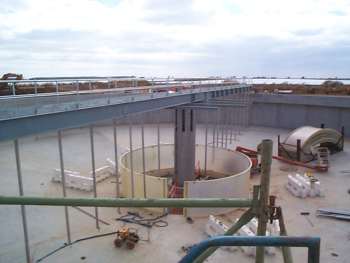
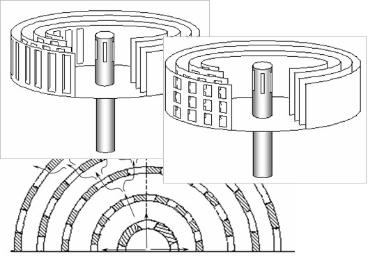
What were previously available
Various types of energy dissipating devices have been developed for dissipating the energy of the
influent entering into a flocculation well in the center-feed clarifiers. The traditional Energy Dissipating
Inlet (EDI) has often been used in many recent clarifier designs with the center-feed structure in order to
dissipate the clarifier inlet energy. Using the traditional EDI shown in Figure, the jet of clarifier influent
flow through a few influent ports is still very strong due to the small cross sectional area of the ports,
especially in a large clarifier and under high flow conditions.
If the cross sectional area of the inlet ports is simply enlarged, flow short-circuiting (or unevenly
distributed flow) may occur among the ports due to lack of flow impingement between the influent and
the EDI. The over sized EDI inlet ports may cause insufficient resistance along the radius.
Using previously available EDIs, the strong influent jet impingement occurs either outside the wall of the
EDI or underneath the bottom of the EDI. The turbulence in clarifiers must be lowered in order to control
the dispersed sludge blanket. Any EDI alternatives having either the intensive inlet jets or the strong flow
impingement among the jets occurred outside the EDI column may not be able to effectively confine the
turbulence entering into clarifiers.

Overloaded Clarifiers and Dispersed Sludge Blanket
The existing secondary clarifiers at Western Treatment Plant, Melbourne,
often experience very high effluent TSS due to the impact of a massive sludge
inventory. In the overloaded clarifiers, the effluent TSS (and BOD) is extremely
sensitive to any minor variations in plant flow. This is because the top of
sludge blanket is close to the surface and can easily be carried over the
effluent weirs. The overloaded conditions can often cause a large unexpected
loss of bio-solids from the secondary treatment process.The flow capacity for
the four existing clarifiers studied ranges from 115 to 145 ML/day due to
variations of the process parameters (sSVI and MLSS). The clarifiers are
unable to achieve their expected design flow of 190 ML/day due primarily to
the thickening limitation of clarifiers.
What should be the principles for any effective EDIs
The turbulence in clarifiers must be lowered in order to control the dispersed
sludge blanket under high flow or solids loading conditions.
To produce satisfactory hydraulic behavior, one of the necessary design
conditions is that the cumulative space of the inlet ports of an EDI must be big
enough. However, this condition alone is not sufficient to guarantee a low
momentum entering into the clarifiers. An optimized design of clarifier inlet
structure should simultaneously satisfy both working principles, i.e. a large
accumulative space of inlet ports and sufficient impingement between the
influent flow and EDI column(s) to create an uniform flow distribution among
the inlet ports in the outside wall of EDI.
An innovative “Multilayer Energy Dissipating Inlet Column” (MEDIC) could be
used as an effective solution to the problem of strong center-feed jets.
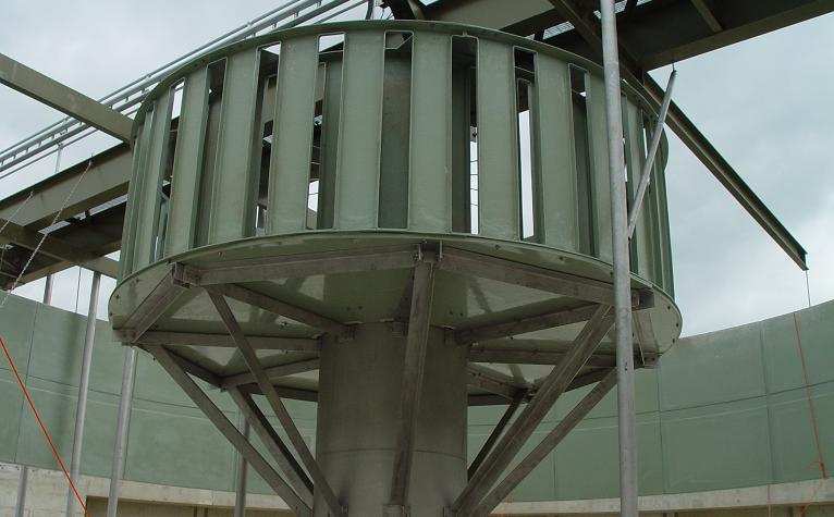
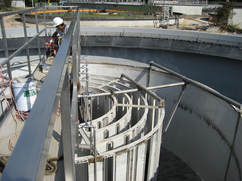
Multilayer Energy Dissipating Inlet Column (MEDIC)
MEDIC consists of the following 3 major components:
Each of the perforated and concentric columns has different radii. In the
wall of each perforated column many flow inlet ports are mounted for flow
going through. The layout of the flow inlet ports between any two adjacent
perforated columns must be staggered along both the tangential and
vertical direction or otherwise staggered along at least one direction of
them in order to create a puzzled flow path and flow impingement on each
layer of the MEDIC. A circular cover closes the bottom of the multilayer
column and the small drainage holes are distributed on the bottom cover
(US Patent No. 7378027).
MEDIC consists of the following 3 major components:
- A center influent pipe, which has several flow influent ports in the
wall of the pipe located between sludge blanket and clarifier liquid
surface; - A plurality of perforated and concentric columns;
- A circular cover, which closes the bottom of the multilayer column.
Each of the perforated and concentric columns has different radii. In the
wall of each perforated column many flow inlet ports are mounted for flow
going through. The layout of the flow inlet ports between any two adjacent
perforated columns must be staggered along both the tangential and
vertical direction or otherwise staggered along at least one direction of
them in order to create a puzzled flow path and flow impingement on each
layer of the MEDIC. A circular cover closes the bottom of the multilayer
column and the small drainage holes are distributed on the bottom cover
(US Patent No. 7378027).
Comparison of Clarifier Performance with and without MEDIC
The operations for the clarifier equipped with a simple center
influent pipe indicate:
1. The strong influent jet through the inlet ports penetrates the
entire radius of the flocculation well and impinges on the inner
side of the well due to the lack of effective momentum or energy
dissipating facilities within the flocculation well. After impinging
on the flocculation well, the influent flow deflects and forms a very
strong downward current toward the sludge blanket and clarifier
floor.
2. Significant reverse flow is predicted underneath the strong
surface influent jet due to the shears between them.
3. A pinched clarifier influent flow under the baffle lip can be
observed due to the massive sludge inventory in the clarifier. The
density forward current is much closer to the water surface than
that occurred under a lower flow condition due to the buoyancy
impact of the thick sludge blanket.
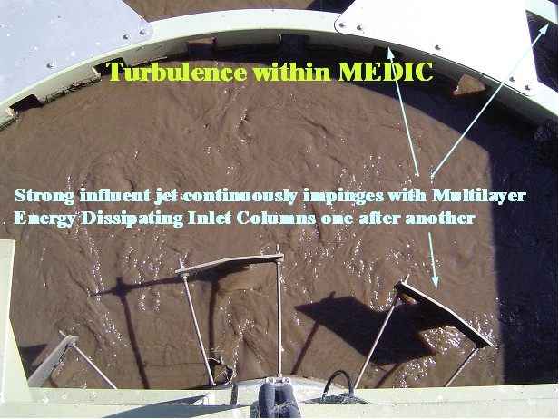
At the same plant, the operations for the clarifiers equipped with a MEDIC indicate:
1. The strong influent jet due to the small influent ports continuously impinges with the
multilayer perforated columns one after another. The velocities of the influent jets have been
substantially reduced before and after going through the ports in the last perforated layer.
The resistance created by the multiple perforated columns forces the influent jet to be
sufficiently distributed along the vertical and tangential directions before it enters into the
flocculation well.
2. The downward current due to the deflection of the influent jet on the flocculation well
has been significantly reduced, since the momentum of the influent jet is effectively
dissipated by applying the MEDIC. The circular bottom forces all of the influent flow going
through the staggered ports and prevents flow short circuiting between the inlet ports and
flocculation well.
3. The pinched flow underneath the lip of the baffle (flocculation well) has been
eliminated and the level of density forward current is much closer to the clarifier floor due to
the lowered turbulence and the well controlled dispersed sludge blanket in the clarifier.
4. The significant reverse flow underneath the surface influent jet predicted in the existing
clarifiers has been almost eliminated, since the significantly slowed influent jet generates a
much weaker shear influence on the ambient flow.
Clarifier Capacity Enhancement
The clarifiers with no MEDIC have a flow capacity of 1200 ~ 1470 (m3/h per tank) under the normal process condition, which is most of the year. The
clarifiers equipped with MEDIC above achieve a flow capacity higher than 2000 (m3/h, per tank). MEDIC provides at least 30% more capacity for the
upgraded clarifiers.

| |||||||

| ||||||||||
| ||||||||||||||||||||||||||||||||||||||||||||||||||||||||||||||||||||||||||
| ||||||||||||||||||||||||||||||||||||

| |||||||||||||||||||||||||||||||||||||||||||||||||||||||||||||||||||||||||||||||||


|

Copyright © 2005-2008 Hydrosims. All rights reserved.
Traditional
EDI
EDI